CONNECTION TUTORIAL 2
Timber truss apex with plywood gusset plates
brief
A connection is required to connect the timber members at the apex of a truss. The post is 100 x 50 mm while the rafters are 125 x 50 mm (Figure 1). All truss members are of strength class C18 softwood [BS EN 338:2009]. The connection will be made with gusset plates of Finnish birch plywood, with a thickness of 12 mm. The gusset plate has a clear coverage of 250 mm in the rafters and 100 mm in the post (Figure 1).The face grain is horizontal to the connection.
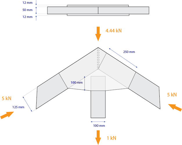
Figure 1: Members to be connected
The fasteners that will be used are nails with a tensile strength . The diameter of the nails is (head diameter ). The length of the nails is .
The design action is (compressive) on each rafter and (tensile) on the post, composed of a permanent component and a medium-term component (Figure 1). The connection operates in Service Class 2 conditions.
The designer decides to employ 6 nails on each side of each rafter, and 2 nails on the post. All nails will be arranged in a staggered pattern.
In the rafters, the spacing between columns is , and the spacing between rows is (Figure 2). The end distances are and .
In the post, the spacing between columns is , and the spacing between rows is (Figure 2). The end distances are and .
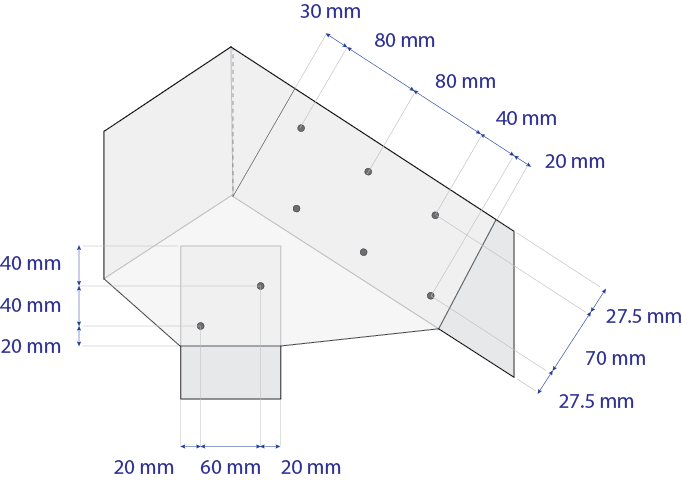
Figure 2: Suggested fastener pattern
Check this connection with Teretron, determining if it passes the strength check and if it fulfills the minimum distance and other requirements. Also, verify the strength of all timber and plywood members. There is no requirement to verify against fire.
solution
1. Modelling the members
As the rafters are symmetrical, only one needs to be checked. Both connections are single-shear timber-to-plywood, with fasteners in a staggered arrangement (Figure 2).
The members that need to be checked is one rafter (in compression)and the post (in tension). Also, the gusset plate needs to be checked in both tension and compression.
2. Creating a new folder
As there are two connections and four member checks, a folder is needed to contain all the components.
Click on Folder > New Folder (keyboard shortcut Alt > L > N) or alternatively right-click on the Folder Tree and click on New Folder(Figure 4).
Rename the folder by single-clicking on the name, or by hitting the F2 key.
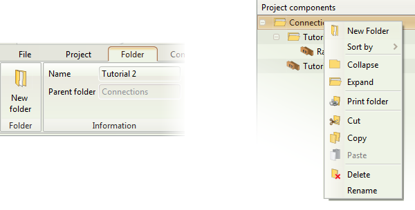
Figure 3: Create a new folder
3. Creating the Rafter Connection
Click on Folder > Connections > Connection under tension or alternatively on Component > New Component > Connections > Connection under tension (Figure 4) to create a new connection.
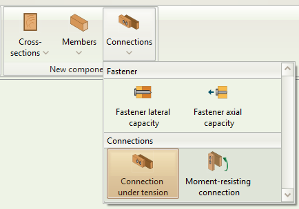
Figure 4: Select Connection under tension
4. Rafter Connection: Member inputs
Click on the new component on the folder tree to rename it. Double click to activate it (Figure 5).
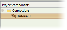
Figure 5: Rename and activate component
Input the data for the connection. Click on the timber class box to select the strength class (Figure 6). You can also see the specific properties associated with each strength class (for r2015 and previous, hover the mouse cursor over the strength class).

Figure 6: Select timber strength class
You can model the ends of the connection in order to get the respective checks for end distances. The End input refers to where each member closes. If a member is Continuous no end checks will be performed.
The end distance refers to the distance between the center of the connection and the end.
In this case, the distance between the end of the connection and the center is 150 mm (Figure 7). The plywood gusset plate can be taken as closed on Both Sides, while the rafter closed on one side.
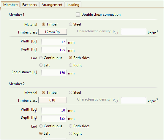
Figure 8: Rafter Connection, Member inputs
While modelling the connection, you can see the respective graphics on the right-hand side (Figure 8).
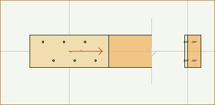
Figure 8: Rafter Connection graphics
5. Rafter Connection: Fastener inputs
Click on the Fasteners tab to input the fastener data as per the brief (Figure 9).
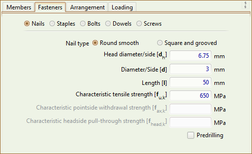
Figure 9: Rafter Connection, Fastener Data
6. Rafter Connection: Arrangement input
Click on the Arrangement tab to input the arrangement data as per the brief (Figure 10).
Note that in staggered connections the number of columns assumes that the fasteners on odd and even rows belong to different columns. Hence in this case, to arrange 6 nails in 2 rows, we need to set 6 columns.
 Figure 10: Rafter Connection, Arrangement inputs
7. Rafter Connection: Loading inputs
Click on the Loading tab to input the loading data as per the brief (Figure 11).
As the connection is composed of two gusset plates (each in single shear), the tensile force carried by each single-shear connection is 2.5 kN.
As the design force has both a permanent and a medium-term component, the total load-duration class is taken as Medium-term (a separate check should be done for the permanent component only, as per EC0 guidance).
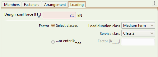
Figure 11: Rafter Connection, Loading inputs
8. Rafter Connection: Checking the Results and the Calculations
Once you finish inputting the minimum required amount of data to check a connection, Teretron can verify the connection in the background.
The Results tab is populated so you can check out how the connection is performing with these inputs (Figure 12).
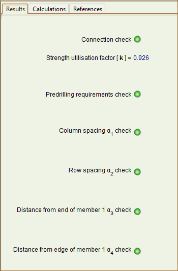
Figure 12: Rafter Connection, Results tab
The overall state of the component can be seen both at the Component ribbon (Figure 13) and the top of the screen (Figure 14). The left indicator shows the state of the entire project, while the right indicator shows the state of the currently active component.
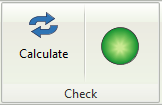
Figure 13: Check state on the Component ribbon

Figure 14: Check state on the top of the screen
To see the full calculations, click on the Calculate button on the ribbon (Figure 13) or simply hit F5.
This will activate the Calculations and References tabs on the Outputs area. You can now see the calculations in detail (Figure 15).

Figure 15: Calculations tab
9. Creating the Post Connection
You can, as before, click on Folder > Connections > Connection under tension or alternatively on Component > New Component > Connections > Connection under tension (Figure 4) to create a new connection.
However, given that many inputs are similar between the two connections, it is quicker to Copy and Paste the connection.
With the rafter connection activated, click on Component > Copy, or alternatively right click on the folder tree and select Copy (Figure 17). Then paste the component either from the ribbon Component > Paste or by right-clicking on the destination folder on the folder tree and selecting Paste (Figure 18).
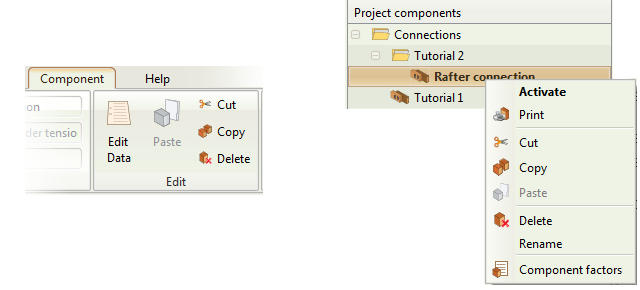
Figure 16: Copy component
10. Post Connection: Member inputs
Click on the new component on the folder tree to rename it. Double click to activate it (Figure 5).
Alter the data to reflect the post connection. As the timber classes are similar, what you need to edit is the depth of the post ().
Note that Teretron sets the timber grain parallel to the horizontal axis of the screen. Hence we need to view the connection in a angle compared to how it is in reality.
As before, the end distance refers to the distance between the center of the connection and the end. In the post, the distance between the end of the connection and the center is (Figure 18). The plywood gusset plate can be taken as closed on Both Sides, while the post closed on one side.
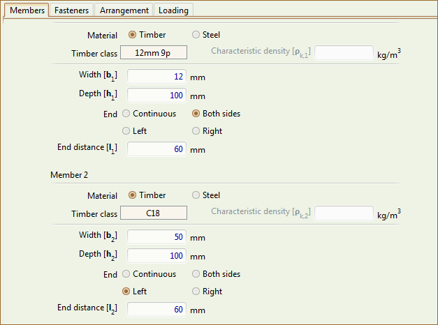
Figure 17: Post Connection, Member inputs
While modelling the connection, you can see the respective graphics on the right-hand side (Figure 18)
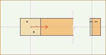
Figure 18: Post Connection graphics
11. Post Connection: Fastener inputs
Click on the Fasteners tab to see the fastener data.
As we've copied the component and we are using the same nails, no change is required.
12. Post Connection: Arrangement inputs
Click on the Arrangement tab to input the arrangement data as per the brief (Figure 19).
As before, note that in staggered connections the number of columns assumes that the fasteners on odd and even rows belong to different columns. Hence in this case, to arrange 2 nails in 2 rows staggered, we need to set 2 columns.
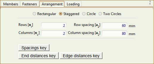
Figure 19: Post Connection, Arrangement inputs
13. Post Connection: Loading inputs
Click on the Loading tab to input the loading data as per the brief (Figure 20).
As the connection is composed of two gusset plates (each in single shear), the tensile force carried by each single-shear connection is .
As the design force has both a permanent and a medium-term component, the total load-duration class is taken as Medium-term (a separate check should be done for the permanent component only, as per EC0 guidance).
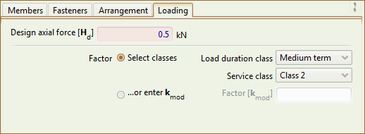
Figure 20: Post Connection, Loading inputs
14. Post Connection: Checking the Results and the Calculations
The Results tab is populated instantly (Figure 21).
![][fig 21]
Figure 21: Post Connection, Results tab
To see the full calculations, click on the Calculate button on the ribbon or simply hit F5. This will activate the Calculations and References tabs on the Outputs area. You can now see the calculations in detail (Figure 22).
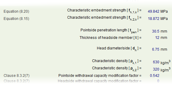
Figure 22: Post Connection, Calculations tab
15. Check the rafter against compression
Each rafter is under compression parallel to the grain. Create the respective design case from the Ribbon (Folder > Cross-sections > Compression parallel to the grain or Component > New Component > Cross-sections > Compression parallel to the grain).
Input the member data as before. The maximum area reduction is (3 mm diameter in a 150 mm cross-section) (Figure 22).
The truss allows redistribution of stresses and hence the respective box can be clicked to take into account the factor (Figure 23).
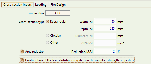
Figure 23: Rafter strength check, Members tab
The loading is on each rafter (Figure 25). The Load Duration class for the combined design load is Medium-term (note that the rafter should be checked separately against the permanent load only).

Figure 24: Rafter strength check, Loading tab
As there is no requirement to check the members in case of fire, the Fire Design tab inputs can be ignored.
The Results tab is populated instantly and you can hit F5 or click on Component > Calculate to activate the Calculations and References tabs (Figure 25).

Figure 25: Rafter strength check, Calculations tab
16. Check the post against tension
The post is under tension parallel to the grain. Create the respective design case from the Ribbon (Folder > Cross-sections > Tension parallel to the grain or Component > New Component > Cross-sections > Tension parallel to the grain).
Input the member data as before. The maximum area reduction is (3 mm diameter in a 100 mm cross-section). The truss allows redistribution of stresses and hence the respective box can be clicked to take into account the ksys factor (Figure 26).
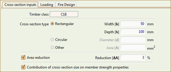
Figure 26: Post strength check, Members tab
The loading on the post is (Figure 27). The Load Duration class for the combined design load is Medium-term (note that the rafter should be checked separately against the permanent load only).

Figure 27: Post strength check, Loading tab
As there is no requirement to check the members in case of fire, the Fire Design tab inputs can be ignored.
The Results tab is populated instantly and you can hit F5 or click on Component > Calculate to activate the Calculations and References tabs (Figure 28).
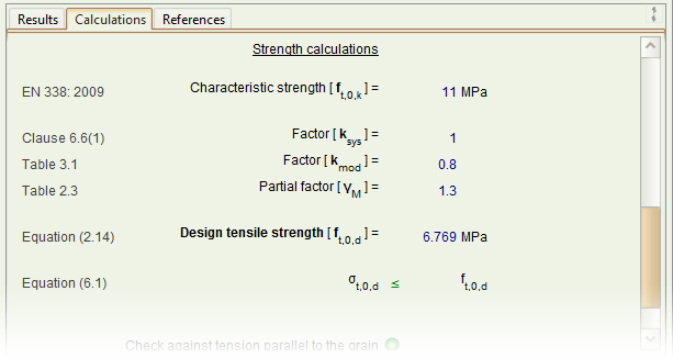
Figure 28: Post strength check, Calculations tab
17. Check the plywood gusset plate against axial loading
The gusset plate is under compression parallel to the grain in the rafter area, and under tension perpendicular to the grain in the post area.
Create the respective design cases from the Ribbon (Folder > Cross-sections > Tension perpendicular to the grain or Component > New Component > Cross-sections > Tension perpendicular to the grain,
and
Folder > Cross-sections > Compression parallel to the grain or Component > New Component > Cross-sections > Compression perpendicular to the grain).
Input the member data as before. The area under axial loading can be taken to be in the post, and in the rafter.
The area reduction due to nails can be ignored.
There is no redistribution of stresses in the gusset plate (Figure 25).

Figure 29: Gusset plate strength checks, Members tab
The compressive loading on each plate in the rafter area is ( (5 x cos33°) / 2 ).
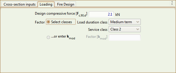
Figure 30: Gusset plate strength checks, Compression parallel to the grain
The tensile loading on each plate in the post area is .
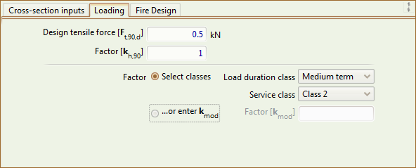
Figure 31: Gusset plate strength checks, Tension perpendicular to the grain
As there is no requirement to check the members in case of fire, the Fire Design tab inputs can be ignored.
The Results tab is populated instantly and you can hit F5 or click on Component > Calculate to activate the Calculations and References tabs (Figure 27).
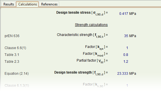 Figure 32: Gusset plate strength checks, Calculations tab
DISCLAIMER: The brief for this tutorial has been adopted from an example in the authoritative volume "Structural Timber Design to Eurocode 5" by Dr Jack Porteous and Prof Abdy Kermani, one of the major reference works for timber to any design code. To see the original example and the authors' extensive solution you can purchase the book here.