CONNECTION TUTORIAL 1
Checking a timber-to-timber tension splice connection
brief
A splice connection is required to connect two timber members. Each member is 60 x 145 mm. The side members are 35 x 145 mm (Figure 1) with a length of 412 mm. All members are of strength class C22 softwood [BS EN 338:2009].
A splice connection is required to connect two timber members. Each member is 60 x 145 mm. The side members are 35 x 145 mm (Figure 1) with a length of 412 mm. All members are of strength class C22 softwood [BS EN 338:2009].
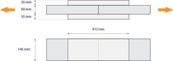
Figure 1: Members to be connected
The fasteners that will be used are nails with a tensile strength . The diameter of the nails is (head diameter ). The length of the nails is .
The design action is (tensile) composed of a permanent component and a medium-term component, while the connection operates in Service Class 2.
The designer decides to employ 18 nails on each side member, on a 3x3 rectangular pattern. The spacing between columns is , and the spacing between rows is (Figure 2).
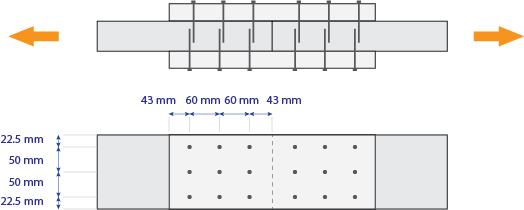
Figure 2: Suggested fastener pattern
Check this connection with Teretron, determining if it passes the strength check, if it fulfills the minimum distance and other requirements.
solution
1. Modelling the connection
As the connection is symmetrical on both sides, and on both members, what needs to be checked is one side and one member. The connection is effectively a single-shear timber-to-timber one, with fasteners in a rectangular arrangement (Figure 3).
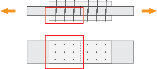
Figure 3: Connection to be modelled
2. Creating a new connection
Click on Folder > Connections > Connection under tension or alternatively on Component > New Component > Connections > Connection under tension (Figure 4) to create a new connection.
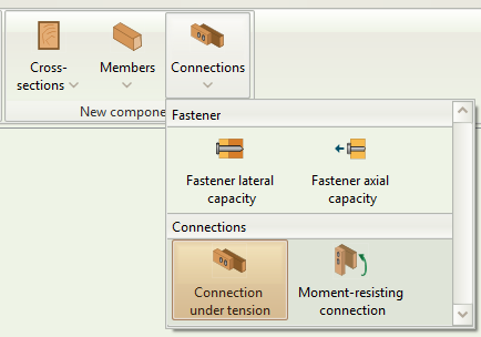
Figure 4: Select Connection under tension
3. Member data inputs
Click on the new component on the folder tree to rename it. Double click to activate it (Figure 5).

Figure 5: Rename and activate component
Input the data for the connection. Click on the timber class box to select the strength class (Figure 6). You can also hover over the mouse cursor to see the specific properties associated with each strength class.

Figure 6: Select timber strength class
You can model the ends of the connection in order to get the respective checks for end distances. The End input refers to where each member closes. If a member is Continuous no end checks will be performed.
The end distance refers to the distance between the center of the connection and the end.
In this case, the distance between the end of the connection and the center is 103 mm (Figure 7), as each side of the splice is 206 mm (Figure 1).
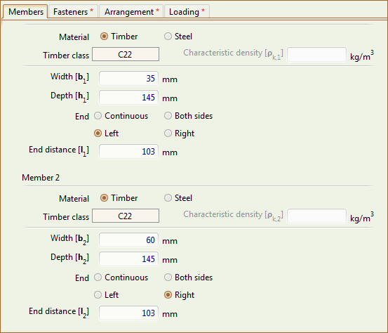
Figure 7: Member Inputs
While modelling the connection, you can see the respective graphics on the right-hand side (Figure 8)
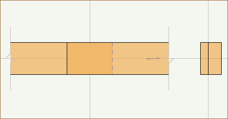
Figure 8: Connection graphics
4. Fastener inputs
Click on the Fasteners tab to input the fastener data as per the brief (Figure 9).
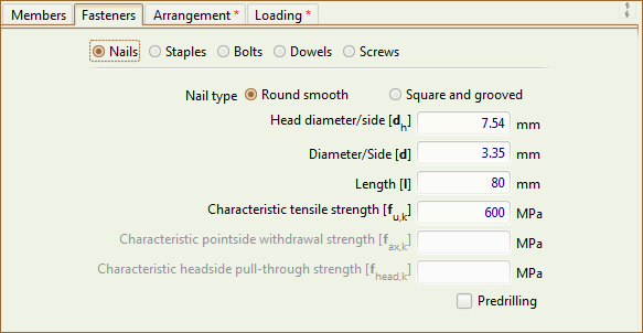
Figure 9: Fastener data
5. Arrangement inputs
Click on the Arrangement tab to input the arrangement data as per the brief (Figure 10).
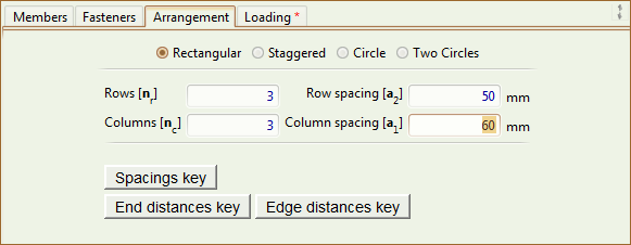
Figure 10: Arrangement data
6. Loading inputs
Click on the Loading tab to input the loading data as per the brief (Figure 11).
As the connection is composed of two splices (each in single shear), the tensile force carried by each splice is 4 kN.
As the design force has both a permanent and a medium-term component, the total load-duration class is taken as Medium-term (a separate check should be done for the permanent component only, as per EC0 guidance).

Figure 11: Loading data
7. Checking the Results and the Calculations
Immediately after you finish inputting the minimum required amount of data to check a connection, Teretron starts verifying the connection in the background. The Results tab is populated instantly so you can check out how the connection is performing with these inputs (Figure 12).
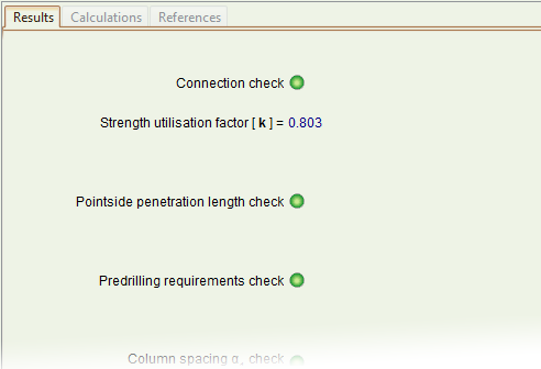
Figure 12: Results tab
The overall state of the component can be seen both at the Component ribbon (Figure 13) and the top of the screen (Figure 14). The left indicator shows the state of the entire project, while the right indicator shows the state of the currently active component.

Figure 13: Check state on the Component ribbon

Figure 14: Check state on the top of the screen
To see the full calculations, click on the Calculate button on the ribbon (Figure 13) or simply hit F5.
This will activate the Calculations and References tabs on the Outputs area. You can now see the calculations in detail (Figure 15).
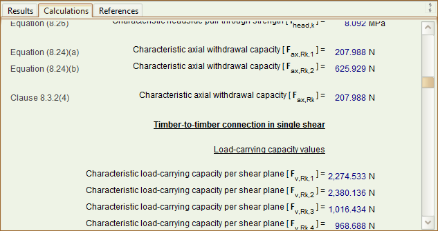
Figure 15: Calculations tab
8. Adjusting the results
With the numbers tried in this example, the design passes the check with regard to strength, but fails with regard to the end distances. The minimum required end distance is 50.25 mm as opposed to the 43 mm allowed for by the designer (Figure 16).

Figure 16: Distances and spacings calculation
The designer can adjust the column and row spacings. Note that you can simply use the mouse roller over number input boxes. Teretron will recalculate the result at each input so you can identify the critical point at which a check passes or fails.
The designer finally selects column and row spacings of 45 mm (Figure 17).
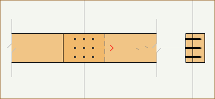
Figure 17: Modified fastener arrangement
The connection now satisfies all the Eurocode 5 requirements and the designer can move on the next component!

Figure 18: Checks passed!
DISCLAIMER: The brief for this tutorial has been adopted from an example in the authoritative volume "Structural Timber Design to Eurocode 5" by Dr Jack Porteous and Prof Abdy Kermani, one of the major reference works for timber to any design code. To see the original example and the authors' extensive solution you can purchase the book here.