CONNECTION TUTORIAL 5
Knee brace under wind loading
brief
A diagonal knee brace is to be connected with a column. The knee brace is composed of two pieces of C30 softwood, each with a 75 x 175 mm cross-section, at an angle of 45° to the horizontal. The column is composed of two C30 pieces, with 75 x 300 mm cross-sections.
The two members will be connected via a C30 packing piece of a 150 x 175 mm cross-section. (Figure 1)
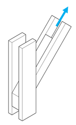
Figure 1: Knee brace and column with packing piece
The knee brace is under axial wind loading with a design value of Fd = 50 kN. The structure operates under Service Class 2 conditions.
The fasteners that will be used for both connections are M20 8.8 bolts, with 60 mm washers.
Design and check the two connection (knee brace to packing piece; column to packing piece) against the wind loading.
Also verify the capacity of the column against the shear component of the force.
solution
1. Modelling the connection
We need two connections: one to connect the packing piece to the knee brace (double shear connection under tension) and one to connect the packing piece to the column (double shear connection under combined tension and shear force).
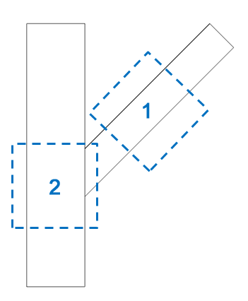
Figure 2: Elevation view of the two connections that need to be designed
2. Creating a new folder
As there are two connections, a folder is needed to contain both the components.
Click on Folder > New Folder (keyboard shortcut Alt > L > N) or alternatively right-click on the Folder Tree and click on New Folder (Figure 3).
Rename the folder by single-clicking on the name, or by hitting the F2 key.
 Figure 3: Create a new folder
3. Creating the knee brace to packing piece connection
Click on Folder > Connections > Connection under tension or alternatively on Component > New Component > Connections > Connection under tension (Figure 4) to create a new connection under tension.
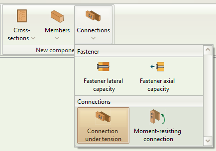
Figure 4: Select Connection under tension
Click on the new component on the folder tree to rename it. Double click to activate it (Figure 5).
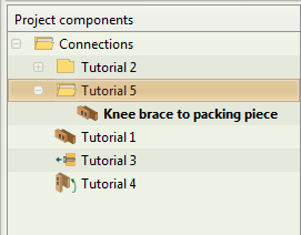
Figure 5: Rename and activate component
4. Connection 1: Member inputs
Input the member data for the connection. Click on the timber class box to select the strength class (Figure 6). You can also hover over the mouse cursor to see the specific properties associated with each strength class.
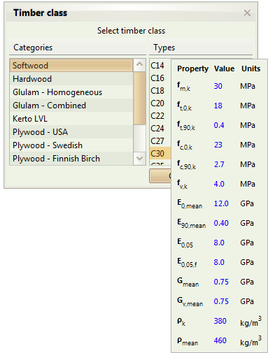
Figure 6: Select timber strength class
Remember that the connection is in double shear, so you need to check the respective box.
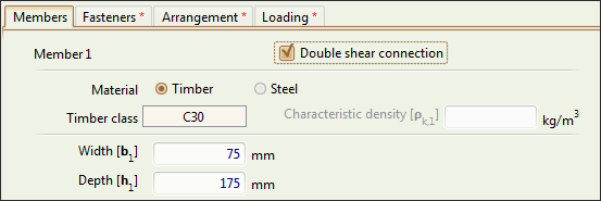
Figure 7: Check double shear box
We decide that the connection area will have a length of 450 mm. This means that the end of each member will be 225 mm from the center of the connection. (Figure 8).
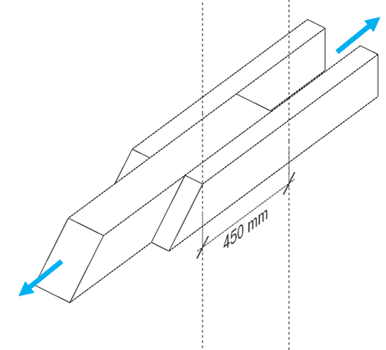
Figure 8: Sketch of the connection area
As we can see from the sketch, the packing piece closes at its right side, while the knee brace at its left side. Both have a distance to the end of . As you type the dimensions, the graphics on the right get updated automatically. The dimension you're typing is also highlighted on the drawing (Figure 9).

Figure 9: Distance of the centre of the connection to the left end of the knee brace
If at any point you're unsure about an input, hover the mouse cursor over the respective input box. A tooltip will appear, providing more information.

Figure 10: Hovering over an input box shows a tooltip with more information.
5. Connection 1: Fastener inputs
Click on the Fasteners tab to input the fastener data as per the brief (Figure 11).
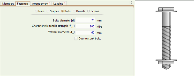
Figure 11: Fastener Data
6. Connection 1: Arrangement inputs
As we have 450 mm, we will use 2 bolts, at a 150 mm spacing. Click on the Arrangement tab to input the arrangement data (Figure 12).

Figure 12: Arrangement inputs
7. Connection 1: Loading inputs
Click on the Loading tab to input the loading data. The wind loading can be taken as short-term; you can always use the tooltip for additional guidance (Figure 13).

Figure 13: Loading inputs
8. Connection 1: Checking the Results and the Calculations
The connection is now fully modelled. To check it, we simply click on the Calculate button on the ribbon (Figure 14) or hit F5 on the keyboard.

Figure 14: Calculate button
This will enable the Results, Calculations, and References tabs on the Outputs area. You can now see the results of the check in detail.
We see that the traffic light next to calculate has turned green (Figure 15).

Figure 15: All checks satisfied
This means that all checks have been satisfied, and thus we can move to the next connection.
We can always see the full set of calculations by clicking on the respective tab (Figure 16).
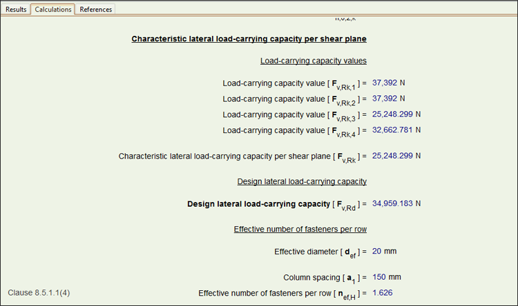
Figure 16: Calculations tab
9. Creating the column to packing piece connection
As this is a connection under combined loading, we will utilise the moment-resisting connection module (simply leaving the moment to zero).
Click on Folder > Connections > Moment-resisting connection or alternatively on Component > New Component > Connections > Moment-resisting connection (Figure 17) to create a new connection that allows combined loading.
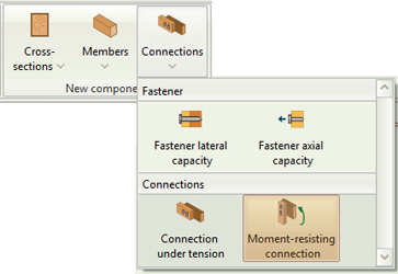
Figure 17: Select Moment-resisting connection
Click on the new component on the folder tree to rename it. Double click to activate it (Figure 18).
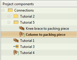
Figure 18: Rename and activate component
10. Connection 2: Member inputs
Input the member data for the connection as per the brief.
The column is an angle of 90 degrees and continuous (Figure 19)
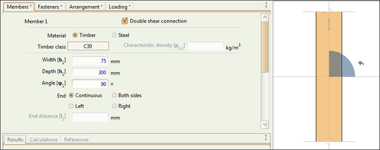
Figure 19: Column data
The knee brace is at an angle of 45 degrees. By measuring or calculating the connection area, we find that it has a length of 424 mm (Figure 20).
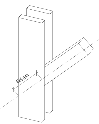
Figure 20: Packing piece sketch
This means that the left end of the packing piece will be 212 mm from the center of the connection. (Figure 21).
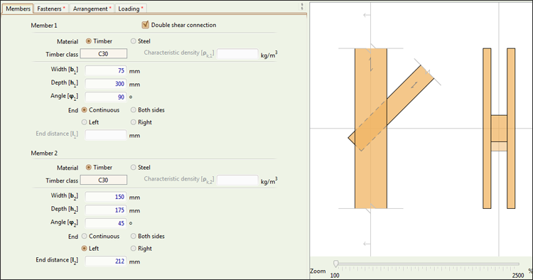
Figure 21: Packing piece data
11. Connection 2: Fastener inputs
Click on the Fasteners tab to input the fastener data as per the brief (Figure 11).
12. Connection 2: Arrangement inputs
We will use 2 bolts, along the grain of the packing piece, at a 175 mm spacing. Click on the Arrangement tab to input the arrangement data (Figure 22).

Figure 22: Arrangement inputs
13. Connection 2: Loading inputs
Click on the Loading tab to input the loading data. The only loading is axial, at an angle of 45 degrees from the horizontal.
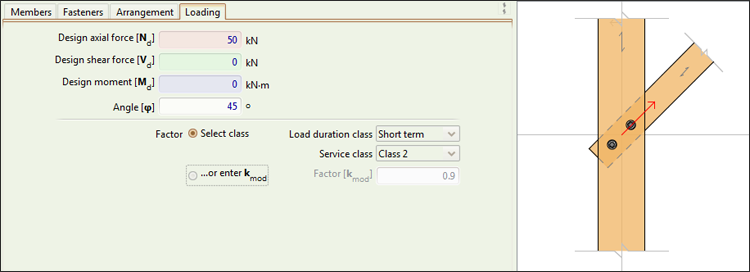
Figure 23: Loading inputs
14. Connection 2: Checking the Results and the Calculations
The connection is now fully modelled. To check it, we simply click on the Calculate button on the ribbon (Figure 24) or hit F5 on the keyboard.

Figure 24: Calculate button
This will enable the Results, Calculations, and References tabs on the Outputs area. You can now see the results of the check in detail.
We see that the traffic light next to calculate has turned green. This means that all checks have been satisfied, and thus we have design the connection successfully.
We can always see the full set of results and calculations by clicking on the respective tabs (Figure 25).

Figure 25: Results tab