CONNECTION TUTORIAL 3
Calculating the axial capacity of a wall cladding fastener
brief
The cladding of a wall is subject to wind suction (Figure 1) The cladding is connected to wall studs, placed at 600 mm centre distances. The cladding is made of 9 mm thick 7p Finnish conifer plywood. The studs are of C16 softwood timber with 44 x 97 mm cross-sections.
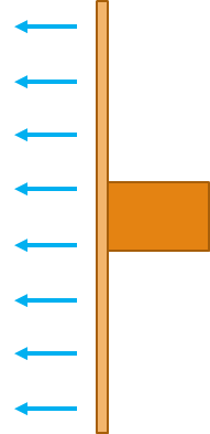
Figure 1: Cladding and studs
The cladding is connected to the studs with smooth round nails, with a diameter and length . The characteristic tensile strength of the nails .
Determine the axial withdrawal capacity of the nails.
solution
1. Creating a new connection
Click on Folder > Connections > Fastener axial capacity or alternatively on Component > New Component > Connections > Fastener axial capacity (Figure 2) to create a new connection.
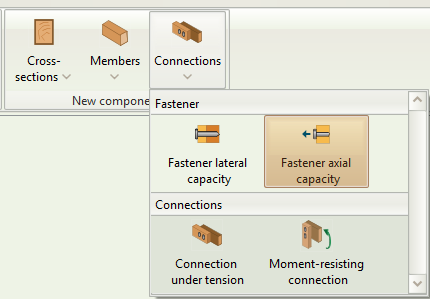
Figure 2: Select Fastener axial capacity
Click on the new component on the folder tree to rename it. Double click to activate it (Figure 3).
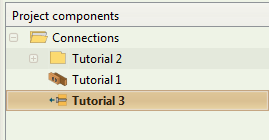
Figure 3: Rename and activate component
2. Member data inputs
Input the data for the connection. Click on the timber class box to select the strength class (Figure 4). You can also hover over the mouse cursor to see the specific properties associated with each strength class.
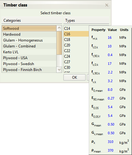
Figure 4: Select timber strength class
The widths of each member refer to the respective cross-sections. Hence for the plywood, and m for the C16 stud.
You can also see the Graphics window on the right hand side. (Figure 5)
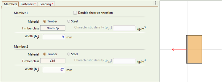
Figure 5: Member data input
3. Fastener inputs
Click on the Fasteners tab to input the fastener data as per the brief (Figure 6).
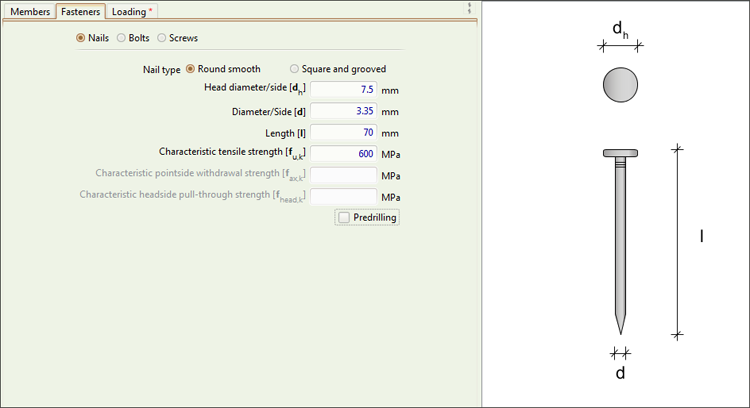
Figure 6: Fastener data
4. Loading inputs
Click on the Loading tab to input the loading data as per the brief.
As the connection is under wind loading, the load duration class will be taken as short term. You can use the tooltip to see the Eurocode guidance for load duration classes and service classes (Figure 7).
![][fig7
Figure 7: Loading data
5. Results and Calculations
To see the full calculations, click on the Calculate button on the ribbon (Figure 8) or simply hit F5.

Figure 8: Calculate button
This will activate the Results, Calculations, and References tabs on the Outputs area. You can now see the calculations in detail (Figures 9-11).

Figure 9: Results tab
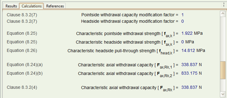
Figure 10: Calculations tab

Figure 11: References tab
Having the design axial capacity of the fastener, we can now decide the required fastener spacings, based on the values of our wind loading.