CONNECTION TUTORIAL 4
Moment-resisting steel flitch connection
brief
A glulam cantilever beam is to be connected to a column with a steel flitch connection. The cantilever has a design medium-term point load at the end with a magnitude . The beam is made of GL24h glulam with a 150 x 320 mm cross-section. (Figure 1)
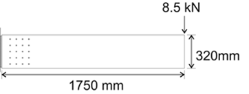
Figure 1: Glulam cantilever
The steel plate has a length of 360 mm (20 mm of which are outside the timber member), a depth of 300 mm, and a thickness of 6 mm.
The fasteners that will be used are M10 4.6 bolts, with 30 mm washers.
Check the connection against maximum lateral loading on the fasteners, minimum distances, brittle failure (splitting), and shear strength of the glulam member.
solution
1. Modelling the connection
As a steel beam is inserted in the glulam member, this is effectively a double-shear steel-to-timber connection.
Each glulam side has a width . This is 150 mm minus 6 mm plate thickness, divided by 2 for each side (Figure 2).
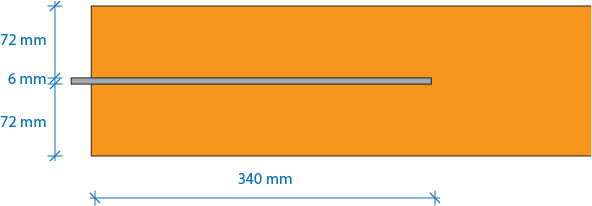
Figure 2: Plan view of the connection
The next step is to decide on a connection. The designer decides to try a 5 x 4 arrangement, with 60 mm distances horizontally and vertically, leaving an 80 mm distance from the left end, and 40 mm distances from the edges (Figure 3).
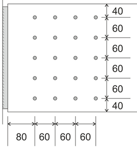
Figure 3: Fastener arrangement
This means that the centre of the connection will be at a distance of 1580 mm from the right end of the cantilever (1750 - 80 - 60 - 30).
This gives a design shear force , and a bending moment () (Figure 4).
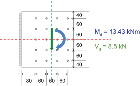
Figure 4: Loading at centre of the connection
2. Create a new moment-resisting connection component
Click on Folder > Connections > Moment-resisting connection or alternatively on Component > New Component > Connections > Moment-resisting connection (Figure 5) to create a new moment-resisting connection.
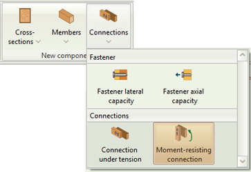
Figure 5: Select Moment-resisting connection
Click on the new component on the folder tree to rename it. Double click to activate it (Figure 6).
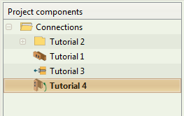
Figure 6: Rename and activate component
3. Member inputs
Input the member data for the connection. Click on the timber class box to select the strength class (Figure 7). You can also hover over the mouse cursor to see the specific properties associated with each strength class.
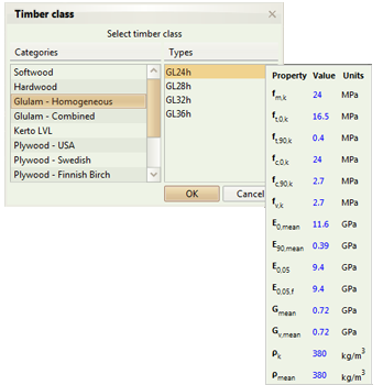
Figure 7: Select timber strength class
Remember that the connection is in double shear, so you need to check the respective box.

Figure 8: Check double shear box
The glulam beam closes at the left. The distance of the centre of axis of the connection from the left end is ().
As you type the dimensions, the graphics on the right get updated automatically. The dimension you're typing is also highlighted on the drawing (Figure 9).

Figure 9: Distance of the centre of the connection to the left end of the beam
Though it doesn't affect the calculations, the steel plate closes on both sides, with a distance from the centre of axis of the connection equal to 190 mm.

Figure 10: Distance of the centre of the connection to the ends of the steel plate
Remember that the end distance refers to the distance between the centre of the connection and the end!.
If at any point you're unsure about an input, hover the mouse cursor over the respective input box. A tooltip will appear, providing more information.

Figure 11: Hovering over an input box shows a tooltip with more information.
4. Fastener inputs
Click on the Fasteners tab to input the fastener data as per the brief (Figure 12).
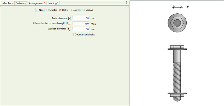
Figure 12: Fastener Data
5. Arrangement inputs
Click on the Arrangement tab to input the arrangement data as per the brief (Figure 13).

Figure 13: Arrangement inputs
6. Loading inputs
Click on the Loading tab to input the loading data as per the brief (Figure 14).
Note that you need to input negative numbers to give the force and member vectors the required direction, as in this case they're opposite of the default.
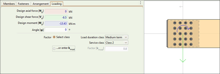
Figure 14: Loading inputs
7. Checking the Results and the Calculations
The connection is now fully modelled. To check it, we simply click on the Calculate button on the ribbon (Figure 15) or hit F5 on the keyboard.

Figure 15: Calculate button
This will enable the Results, Calculations, and References tabs on the Outputs area. You can now see the results of the check in detail.
We can notice that the traffic light next to calculate has turned red (Figure 16).

Figure 16: Failed check
Checking the results on the respective tab we see that, even though the fasteners' lateral capacity checks and minimum distances are satisfied, the connection fails in brittle failure (splitting) (Figure 17).
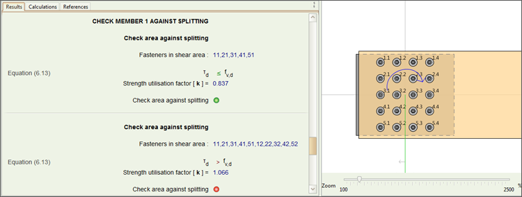
Figure 17: Brittle failure (splitting)
8. Redesigning the connection
Checking the detailed calculations on the Calculations tab, we can see that in order to prevent the failure we need to increase the area under shear (Figure 18).
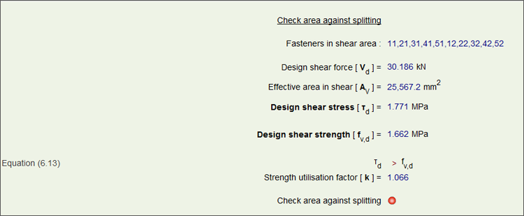
Figure 18: Calculations tab
We increase the beam depth to 350 mm and hit F5 (recalculate).
We see that the traffic light turns green, meaning all the checks are satisfied (Figure 19).

Figure 19: All checks satisfied
As before, we can check the detailed results in the Results and Calculations tabs, as well as see all the assumptions Teretron made at the References tab.
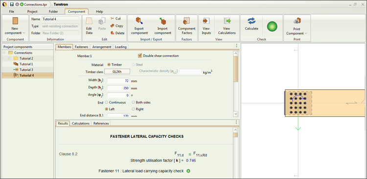
Figure 20: Results tab
note: in moment-resisting connections, Teretron utilises a proprietary algorithm for the check against splitting. This algorithm formed the basis of an academic research paper presented in the World Conference in Timber Engineering in 2014. You can find a summary of the paper here.